")
Description
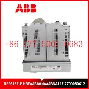
86413006V004VG5M Система возбуждения DCS ABB
CC – Link и другие. Каждый слот IO может быть выбран автономно в соответствии с потребностями клиента, а один модуль поддерживает до 16 каналов.
Технологии основаны на инновациях86413006V004VG5M Предоставление клиентам высококачественных и надежных продуктов всегда было постоянным стремлением к нулю.
Давайте посмотрим на его инновации и различия с предшественниками: с жидкокристаллическим дисплеем, вы можете увидеть параметры связи, состояние канала IO,
информацию о версии модуля и так далее; 86413006V004VG5M Отладка и обслуживание более интуитивно понятны; ABS огнестойкая пластиковая оболочка, небольшой размер,
легкий вес, с использованием совершенно новой пряжки монтажной карты, установка более прочная и надежная.
user experience
Secondly, if power system engineers are to consider the convenience and speed of using the product in the future, operability needs to be improved while ensuring stability.
This requires a simple self-service system and an operation interface with good visual effects that can meet the needs of users. Some operating habits and other aspects
* cut costs
Furthermore, since there are many nodes in the power system, the same product needs to be deployed on many nodes. Then when the quantity of required products increases,
cost issues will inevitably be involved. How to solve the research and development, construction and installation of products and better reduce operating expenses is also a major issue that ABB needs to consider.
Implementation of communication between Omron vision system and ABB industrial robot
introduction
In modern production processes, vision systems are often used to measure and identify products, and then the results are transmitted to industrial robots for work
through communications . In this process, communication settings are very important. This article analyzes the communication implementation process between the Omron
FH-L550 vision system and ABB industrial robots. The main task is to enable the vision system to provide data detection results for ABB industrial robots, and the industrial robots
perform related operations based on the data results. This article mainly discusses the entire process of visual system communication transmission implementation.
1Ethernet-based communication settings in vision software
The main communication methods of Omron FH-L550 vision system controller are as follows [2], namely: parallel communication, PLCLINK communication, Ethernet
communication, EtherCAT communication, and protocol-free communication. These five communication methods have their own characteristics in the communication process.
In modern equipment, Ethernet communication
(Ethernet communication) is the most common, so this article uses the Ethernet communication method as an example to analyze and explain.
First, select the “Tools” option in the main interface, select the “System Settings” menu (Figure 1), after entering the “System Settings” menu, click the “Startup Settings” option,
and select the “Communication Module” tab (Figure 2 ), after completing the above settings, return to the main interface to save the settings (Figure 3). Finally, select the function
menu to perform system restart settings, and wait for the system to complete the restart before proceeding to the next step.
After the system restarts, click the “System Settings” menu again and select the “Ethernet (No Protocol (UDP))” option (Figure 4). In this option, there will be parameter settings
such as IP address and port. What needs to be noted here are the two IP address parameters. The parameters in “Address Setting 2” need to be filled in. The information that needs
to be filled in includes the IP address of the vision controller, subnet mask, default gateway and DNS server.
In the port number setting of “Input/Output Settings” at the bottom of the menu, set the port number for data input with the sensor controller. Note that the port number should
be the same as the host side, and finally complete the settings and corresponding data saving work.
2ABB industrial robot communication settings
First, configure the WAN port IP address for the ABB industrial robot. Select the control panel in the teach pendant, then select configuration, then select communication in
the theme, click IPSetting, set the IP information and click “Change” to save the IP information.
Next, use the SocketCreate robot command to create a new socket using the streaming protocol TCP/IP and assign it to the corresponding variable (Figure 5). Then
use the SocketConnect command to connect the socket to the remote computer. After the communication connection is completed, it is necessary to send and receive
information from the visual system. To send information, use the SocketSend instruction to send data instructions to the remote computer. After the vision system collects
information and makes judgments, the industrial robot system will receive data from the remote computer. The data reception is completed using the
SocketReceive instruction. This instruction stores the data in the corresponding string variable while receiving the data. Useful information needs to be extracted from the
received data information, which requires StrPart to find the specified character position instruction, extract the data at the specified position from the string, and assign the
result to a new string variable. Finally, when the socket connection is not in use, use SocketCloSe to close it.
MTL838C MTL instrument analog transmitter
810-099175-011 LAM Interface board module
DSQC346G 3HAB8101-706B drive unit
5PC810. SX05-00 APC810 system unit
XV 430-12TSB-1-10 EATON 12.1″, TFT color
XV440-10TVB-X-13-1 EATON 10.4 “, TFT color
XV 430-10TVB-1-10 EATON 10.4 inches
XV442-57CQB-X-13-1 ESTON 5.7 inches
XV 432-57CQB-1-10 ESTON 5.7-inch touch screen
XV-440-12TVB-1-50 EATON
XV 440-12TSB-1-10 ESTON Touch panel
XV-440-12TVB-1-50 EATON Man-machine interface
XV 440-12TSB-X-13-1 ESTON 12.1″, TFT Color, i/r, Ethernet, USB, RS232, CANopen
XV442-57CQB-1-10 EATON 5.7 inch, Color, i/r, Ethernet, USB, RS232, CANopen
VE3008 CE3008 KJ2005X1-MQ1 12P6381X042 MQ Controller
05074-A-0122 05704-A-0121 05704-A-0131 honeywell Quad Relay Interface Card
136294-01 BENTLY 3500/62 I/O Module
P0926PA FOXBORO FBM224, FBM230, and FBM231 terminals
VBX01TA ABB Bus Extender
F3430 HIMA Input/output module
P0916FK FOXBORO cable
140471-01 3500/42M I/O Module
F3430 HIMA Relay module F 3430
3500/91-01-01(161204-01+161216-01)bently Communication Gateway Module
LENZE EPL10200-W includes EPZ-10203 CANPT010W3E
UNS0119A-Z,V1 3BHE030579R0001 Automatic voltage regulator
UNITROL 1020 3BHE030579R0003 Indirect Excitation System
UNS0119A-Z,V1 3BHE030579R0001 Automatic voltage regulator
LAIB V3.0_A00 034STN1-01-300-RS
LAIB V3.0_A00 034STN1-00-300-RS
ATKB_V5.0_A01 03ZSTI4-01-501
ATKB_V5.0_A01 03ZSTI4-00-501
FPB_V3.0_A01 03ZSTJ1-00-301-RS
DSPB_V4.0_A02 03ZSTI7-00-402-RS
PUIM V2.0 034STM4-00-200-RS
DUDT_DETECTION_V2.0_A01 03ZSTJ0-00-201-RS
IPB PCB V2.0_A01 03ZSTL6-00-201-RS printed circuit board
IPB PCB V2.0_A01 03ZSTL6-00-201-RS printed circuit board
149992-01 BENTLY 3500/33 calories Relay Output Module
IS220PVIBH1A 336A4940CSP16 GE Vibration Monitor Pack
RH916XZ foxboro FBM247 Fieldbus module
IS420UCSCH2A-C-V0.1-A Four core controller GE
5SHY3545L0010 3BHB013088R0001 3BHE009681R0101 GVC750BE101
FROSOFT MVI56E-MNETXT Enhanced communication module
REXROTH HDS02.2-W040N-HS12-01-FW Servo controller
DEUBLIN 904-120-188
810-234640-312 LAM Printed circuit board
SAIA 52030C10 PCD2.W200 Analog input module
VM600 XIO16T 620-002-000-113 620-003-111-112 VM600 XIO16T
200-595-031-111 VM600 CPUM modular CPU card
VM600 MPC4 200-510-071-113 200-510-111-034 machinery protection module
VM600 XMV16 600-003 620-001-001-116 condition monitoring module for vibration
VM600 IOC4T 200-560-000-018 200-560-101-015 voltage-drop adaptor
VM600 XIO16T 620-002-000-113 620-003-111-112 extended condition monitoring modules
NI-9853 C series CAN interface module


Reviews
There are no reviews yet.