")
Description
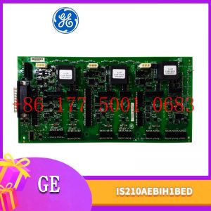
IC694MDL660 Horner Electric
высотой 3U, расположенный в раме управления под DSPX.
волоконно – оптический разъем на передней панели и передаются в модуль обнаружения заземления.

ABB: Запасные части для промышленных роботов серии DSQC, Bailey INFI 90, IGCT, например: 5SHY6545L0001 AC1027001R0101 5SXE10 – 0181, 5SHY3545 L0009, 5SHI3545L0010 3BHB013088 R0001 3BHE009681R0101 GVC750BE101, PM866, PM861K01, PM864, PM510V16, PPD512, PPPD113, PP836A, P865A, 877, PPP881, PPPP885, PPSL500000 4 3BHL00390P0104 5SGY35L4510 и т.д.
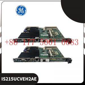
General Electric: запасные части, такие как модули, карты и приводы. Например: VMVME – 7807, VMVME – 7750, WES532 – 111, UR6UH, SR469 – P5 – HI – A20, IS230SRTDH2A, IS220PPDAH1B, IS215UCVEH2A, IC698CPE010, IS200SRTDH2ACB и т.д.
Система Bently Nevada: 350 / 3300 / 1900, предохранительные зонды и т.д., например: 3500 / 22M, 3500 / 32, 3500 / 15, 3500 / 23500 / 42M, 1900 / 27 и т.д.
Системы Invis Foxboro: Серия I / A, управление последовательностью FBM, трапециевидное логическое управление, обработка отзыва событий, DAC,
обработка входных / выходных сигналов, передача и обработка данных, такие как FCP270 и FCP280, P0904HA, E69F – TI2 – S, FBM230 / P0926GU, FEM100 / P0973CA и т.д.
Invis Triconex: Модуль питания, модуль CPU, модуль связи, модуль ввода – вывода, например 300830937214351B, 3805E, 831235114355X и т.д.
Вудворд: контроллер местоположения SPC, цифровой контроллер PEAK150, например 8521 – 0312 UG – 10D, 9907 – 149, 9907 – 162, 9907 – 164, 9907 – 167, TG – 13 (8516 – 038), 8440 – 1713 / D, 9907 – 018 2301A, 5466 – 258, 8200 – 226 и т.д.
Hima: модули безопасности, такие как F8650E, F8652X, F8627X, F8678X, F3236, F6217, F6214, Z7138, F8651X, F8650X и т.д.
Honeywell: Все платы DCS, модули, процессоры, такие как: CC – MCAR01, CC – PAIH01, CC – PAIH02, CC – PAIH51, CC – PAIX02, CC – PAON01, CC – PCF901, TC – CR014, TC – PD011, CC – PCNT02 и т.д.
Motorola: серии MVME162, MVME167, MVME172, MVME177, такие как MVME5100, MVME5500 – 0163, VME172PA – 652SE, VME162PA – 344SE – 2G и другие.
Xycom: I / O, платы VME и процессоры, такие как XVME – 530, XVME – 674, XVME – 957, XVME – 976 и т.д.
Коул Морган: Сервоприводы и двигатели, такие как S72402 – NANA, S6201 – 550, S20330 – SRS, CB06551 / PRD – B040SSIB – 63 и т. Д.
Bosch / Luxer / Indramat: модуль ввода / вывода, контроллер PLC, приводной модуль, MSK060C – 0600 – NN – S1 – UP1 – NNN, VT2000 – 52 / R900033828, MHD041B – 144 – PG1 – UN и т.д.
Figure 4 Tool Framework
2.3Smart component creation
Call the Rotator component: This component is used to allow the rotatable grinding rotor to rotate during simulation to simulate the real grinding scene. In the
parameters of the Rotator component, set the reference to object, the reference object to the frame l, and the object to a copy of the rotor. (2) The rotary grinding rotor
can be rotated, and the speed is l20mm/s (the speed of the grinding head will affect the quality of the finished product) ), the reference center axis is: axis (based on frame
l, centerpoint x, y,: set to 0, 0, 0, Axis set x, y,: 0, 0, l000mm).
Call the Attach component: This component is used to allow the rotatable grinding rotor to be integrated with the tool body. When the tool body is installed
on the flange, it can follow the movement of the flange. In the parameters of the Attach component, set the sub-object to be a copy of the rotor (2) for the rotatable
polishing rotor, and the parent object is the tool body of a copy of the rotor. The offset and orientation are
based on the offset of point B relative to the origin. For setting, you can use the measurement tool in Robotstudio software to measure, and then set the parameters
after measurement.
Verification: Install a copy of the rotor tool body onto the robot flange, and then click Execute in the Attach component. You can observe whether the position of the
rotatable grinding rotor is correct at this time. If there is a deviation, adjust the position in time, as shown in the figure. 5 shown.
Figure 5 Tool installation
2.4 Create tool coordinate system
Use the six-point method to create the tool coordinate system Too1data on the robot teach pendant at the center of the rotor. Change the tool coordinate
system to Too1data in the basic options. At this time, click on the robot manual linear and you can drag the robot to move linearly at will.
2.5 Creating trajectories and programming
Determine the trajectory: According to the requirements of the work task, design the grinding trajectory around the workpiece and determine the trajectory
points and transition points required for the grinding trajectory. The grinding action process is shown in Figure 6.
Setting I/O and programming: Yalong IY-l3-LA industrial robot deburring and grinding system control and application equipment adopts 0sDC-52 6/o
communication board, the address is 10, Do1 is the digital output signal, the address is 1 . First set the I/O board, then set the I/O digital output signal Di1,
and then program on the simulation teaching pendant. The procedure is as follows:
PRoCmain()
setDo1: Set the Do1 signal to allow the external grinding rotor to start rotating.
waitTime1: The robot stays in place and does not move, waits for 1s, and lets the polishing rotor turn to the specified speed, transition
MoveAbsjjpos10NoEoffs,v1000,z50,Too1data1: The robot moves to the initial point jpos10 above point p10. Point jpos10 is used as the starting
point and end point of the robot”s action.
Move4p10,v1000,z50,Too1data1: Move straight line grinding to point p10
Move4pL0,v1000,z50,Too1data1: Move straight line grinding to pL0 point
Move4p30,v1000,z50,Too1data1: Move straight line grinding to point p30
Move4p40,v1000,z50,Too1data1: Move straight line grinding to p40 point
Move4p10,v1000,z50,Too1data1: Move straight line grinding to point p10
MoveAbsjjpos10NoEoffs,v1000,z50,Too1data1: The robot moves to the initial point jpos10 above point p10
waitTime1: wait 1s, transition
ResetDo1: Reset the Do1 signal to stop the rotor ENDPRoC
2.6 Simulation design and verification
Simulation design: Create a smart component to input the Di1 signal, and use the Di1 signal to simulate the external polishing start signal to
execute the Rotator component and Attach component of the smart component to achieve the visual effect of rotating and polishing the polishing rotor.
In the workstation logic design, the smart component input Di1 signal is associated with the robot Do1 signal, so that the robot signal Do1 can control
the smart component input Di1 signal, thereby controlling the start and stop of the rotation of the polishing rotor.
Verification: In the program of the teaching pendant, first set the pp command to move to Main, and then set the robot startup mode to automatic.
Click play in the simulation of Robotstudio software to verify whether the trajectory is consistent with the assumption, and optimize the path in time for
problems existing in the simulation.
3Summary and outlook
This design is based on the programming simulation of the Yalong Y4-1360A industrial robot deburring system to control the grinding robot workstation.
It covers aspects such as creating a workstation, setting
up tools, creating smart components, creating tool coordinate systems, creating trajectories, programming, simulation design, and verification. Starting
with it, the polishing simulation of the workstation is realized through the smart component function of Robotstudio software. The animation effect is intuitive
and lifelike, which not only facilitates teaching demonstrations, but also facilitates program debugging, and has application value for both production and teaching.
In the planning and design of the workpiece grinding trajectory, according to the different roughness and grinding amount process requirements of the
workpiece, the rotation speed, feed speed, feed amount, and grinding angle of the grinding rotor are also different. The feed amount can be adjusted in
time according to the on-site conditions. , feed speed, rotor speed, grinding angle and other parameters. After appropriate adjustments, the motion trajectory is written with the
corresponding program on the Robotstudio software to further reduce the possibility of robot collisions and singular points contained in the trajectory
during the actual debugging process. ,Optimize paths and improve debugging efficiency.
TRICONEX 4107 TRICONEX COMMUNICATION MODULE
PROCESSOR 958481320201 PROC PLUS Communication module
PROCESSOR 958481321210 PD212 Analog output module
PROCESSOR 958481321220 PD208 I/O expansion card
PROCESSOR 958481321300 PSB Compact input module
PROCESSOR 958481321210 PD212 Control board
PROCESSOR 958481320100 350211080090 Processor module
PROCESSOR 958481321200 350211080320 Network communication card
DDC779BE02 3BHE006805R0002 Medium and high voltage module
VACON PC00459G CM210901 PLC module
IC697CPX928-CD GE Programmable logic controller
IC695CPU320-HS GE central processing unit
IC693MDL655 GE 24 volt DC positive/negative logic input module
IC695CPL410 GE Quad-core processor
IC693MDL340 GE AC output module
IC693CHS392 GE 90-30 series platform is compatible with the extension of the substrate
IC660EBD025 GE two 32-circuit DC modules
IC200EBI001 GE Ethernet network interface Unit
FC-QPP-0002 Honeywell quad-core processor
F8651X HIMA Processing board module
EB501 YOKOGAWA Bus repeater module
DS200SLCCG1AEE GE local Area network (LAN) communication card
DS200KLDBG1ABC GE General Electric Display Board
CQM1H-CPU21 Omron General control system
3531E TRICONEX DIGITAL INPUT MODULE
CP430T-ETH ABB control panel
CG6565/64-2L/8T NMS media processing board
BS4141-0/13.5 TURCK Mini fast connector
ATV61HD45N4 Schneider ATV61 speed drive
A860-2005-T505 FANUC High flexible towed chain cable
AS-BDAU-204 Schneider analog input module
A2H254-16 Enterasys Fast Ethernet edge switch
3500/32 125712-01 Bently Nevada 4-channel relay module
330180-X1-CN Bently Nevada Front sensor
330100-90-01 Bently Nevada Preprocessor system
330100-90-00 Bently Nevada 3300 Preprocessor sensor
8220-DI-IS MTL 16 single-ended input channels
4715KL-05W-B50 NMB Axial flow fan
2711P-T6C5A Allen-Bradley Panelview Plus 600 series operator interface terminal
2711-K10G1 Allen-Bradley Panelview 1000 series
мы организуем фото на складе, чтобы подтвердить
чтобы вернуть их вам. Конечно, мы ответим на ваши озабоченности как можно скорее.


Reviews
There are no reviews yet.