Description
IC698CPE040 General Electric
высотой 3U, расположенный в раме управления под DSPX.
волоконно – оптический разъем на передней панели и передаются в модуль обнаружения заземления.
ABB: Запасные части для промышленных роботов серии DSQC, Bailey INFI 90, IGCT, например: 5SHY6545L0001 AC1027001R0101 5SXE10 – 0181, 5SHY3545 L0009, 5SHI3545L0010 3BHB013088 R0001 3BHE009681R0101 GVC750BE101, PM866, PM861K01, PM864, PM510V16, PPD512, PPPD113, PP836A, P865A, 877, PPP881, PPPP885, PPSL500000 4 3BHL00390P0104 5SGY35L4510 и т.д.
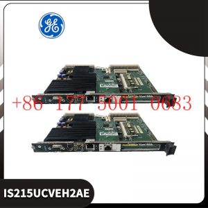
General Electric: запасные части, такие как модули, карты и приводы. Например: VMVME – 7807, VMVME – 7750, WES532 – 111, UR6UH, SR469 – P5 – HI – A20, IS230SRTDH2A, IS220PPDAH1B, IS215UCVEH2A, IC698CPE010, IS200SRTDH2ACB и т.д.
Система Bently Nevada: 350 / 3300 / 1900, предохранительные зонды и т.д., например: 3500 / 22M, 3500 / 32, 3500 / 15, 3500 / 23500 / 42M, 1900 / 27 и т.д.
Системы Invis Foxboro: Серия I / A, управление последовательностью FBM, трапециевидное логическое управление, обработка отзыва событий, DAC,
обработка входных / выходных сигналов, передача и обработка данных, такие как FCP270 и FCP280, P0904HA, E69F – TI2 – S, FBM230 / P0926GU, FEM100 / P0973CA и т.д.
Invis Triconex: Модуль питания, модуль CPU, модуль связи, модуль ввода – вывода, например 300830937214351B, 3805E, 831235114355X и т.д.
Вудворд: контроллер местоположения SPC, цифровой контроллер PEAK150, например 8521 – 0312 UG – 10D, 9907 – 149, 9907 – 162, 9907 – 164, 9907 – 167, TG – 13 (8516 – 038), 8440 – 1713 / D, 9907 – 018 2301A, 5466 – 258, 8200 – 226 и т.д.
Hima: модули безопасности, такие как F8650E, F8652X, F8627X, F8678X, F3236, F6217, F6214, Z7138, F8651X, F8650X и т.д.
Honeywell: Все платы DCS, модули, процессоры, такие как: CC – MCAR01, CC – PAIH01, CC – PAIH02, CC – PAIH51, CC – PAIX02, CC – PAON01, CC – PCF901, TC – CR014, TC – PD011, CC – PCNT02 и т.д.
Motorola: серии MVME162, MVME167, MVME172, MVME177, такие как MVME5100, MVME5500 – 0163, VME172PA – 652SE, VME162PA – 344SE – 2G и другие.
Xycom: I / O, платы VME и процессоры, такие как XVME – 530, XVME – 674, XVME – 957, XVME – 976 и т.д.
Коул Морган: Сервоприводы и двигатели, такие как S72402 – NANA, S6201 – 550, S20330 – SRS, CB06551 / PRD – B040SSIB – 63 и т. Д.
Bosch / Luxer / Indramat: модуль ввода / вывода, контроллер PLC, приводной модуль, MSK060C – 0600 – NN – S1 – UP1 – NNN, VT2000 – 52 / R900033828, MHD041B – 144 – PG1 – UN и т.д.
Figure 4 Tool Framework
2.3Smart component creation
Call the Rotator component: This component is used to allow the rotatable grinding rotor to rotate during simulation to simulate the real grinding scene. In the
parameters of the Rotator component, set the reference to object, the reference object to the frame l, and the object to a copy of the rotor. (2) The rotary grinding rotor
can be rotated, and the speed is l20mm/s (the speed of the grinding head will affect the quality of the finished product) ), the reference center axis is: axis (based on frame
l, centerpoint x, y,: set to 0, 0, 0, Axis set x, y,: 0, 0, l000mm).
Call the Attach component: This component is used to allow the rotatable grinding rotor to be integrated with the tool body. When the tool body is installed
on the flange, it can follow the movement of the flange. In the parameters of the Attach component, set the sub-object to be a copy of the rotor (2) for the rotatable
polishing rotor, and the parent object is the tool body of a copy of the rotor. The offset and orientation are
based on the offset of point B relative to the origin. For setting, you can use the measurement tool in Robotstudio software to measure, and then set the parameters
after measurement.
Verification: Install a copy of the rotor tool body onto the robot flange, and then click Execute in the Attach component. You can observe whether the position of the
rotatable grinding rotor is correct at this time. If there is a deviation, adjust the position in time, as shown in the figure. 5 shown.
Figure 5 Tool installation
2.4 Create tool coordinate system
Use the six-point method to create the tool coordinate system Too1data on the robot teach pendant at the center of the rotor. Change the tool coordinate
system to Too1data in the basic options. At this time, click on the robot manual linear and you can drag the robot to move linearly at will.
2.5 Creating trajectories and programming
Determine the trajectory: According to the requirements of the work task, design the grinding trajectory around the workpiece and determine the trajectory
points and transition points required for the grinding trajectory. The grinding action process is shown in Figure 6.
Setting I/O and programming: Yalong IY-l3-LA industrial robot deburring and grinding system control and application equipment adopts 0sDC-52 6/o
communication board, the address is 10, Do1 is the digital output signal, the address is 1 . First set the I/O board, then set the I/O digital output signal Di1,
and then program on the simulation teaching pendant. The procedure is as follows:
PRoCmain()
setDo1: Set the Do1 signal to allow the external grinding rotor to start rotating.
waitTime1: The robot stays in place and does not move, waits for 1s, and lets the polishing rotor turn to the specified speed, transition
MoveAbsjjpos10NoEoffs,v1000,z50,Too1data1: The robot moves to the initial point jpos10 above point p10. Point jpos10 is used as the starting
point and end point of the robot”s action.
Move4p10,v1000,z50,Too1data1: Move straight line grinding to point p10
Move4pL0,v1000,z50,Too1data1: Move straight line grinding to pL0 point
Move4p30,v1000,z50,Too1data1: Move straight line grinding to point p30
Move4p40,v1000,z50,Too1data1: Move straight line grinding to p40 point
Move4p10,v1000,z50,Too1data1: Move straight line grinding to point p10
MoveAbsjjpos10NoEoffs,v1000,z50,Too1data1: The robot moves to the initial point jpos10 above point p10
waitTime1: wait 1s, transition
ResetDo1: Reset the Do1 signal to stop the rotor ENDPRoC
2.6 Simulation design and verification
Simulation design: Create a smart component to input the Di1 signal, and use the Di1 signal to simulate the external polishing start signal to
execute the Rotator component and Attach component of the smart component to achieve the visual effect of rotating and polishing the polishing rotor.
In the workstation logic design, the smart component input Di1 signal is associated with the robot Do1 signal, so that the robot signal Do1 can control
the smart component input Di1 signal, thereby controlling the start and stop of the rotation of the polishing rotor.
Verification: In the program of the teaching pendant, first set the pp command to move to Main, and then set the robot startup mode to automatic.
Click play in the simulation of Robotstudio software to verify whether the trajectory is consistent with the assumption, and optimize the path in time for
problems existing in the simulation.
3Summary and outlook
This design is based on the programming simulation of the Yalong Y4-1360A industrial robot deburring system to control the grinding robot workstation.
It covers aspects such as creating a workstation, setting
up tools, creating smart components, creating tool coordinate systems, creating trajectories, programming, simulation design, and verification. Starting
with it, the polishing simulation of the workstation is realized through the smart component function of Robotstudio software. The animation effect is intuitive
and lifelike, which not only facilitates teaching demonstrations, but also facilitates program debugging, and has application value for both production and teaching.
In the planning and design of the workpiece grinding trajectory, according to the different roughness and grinding amount process requirements of the
workpiece, the rotation speed, feed speed, feed amount, and grinding angle of the grinding rotor are also different. The feed amount can be adjusted in
time according to the on-site conditions. , feed speed, rotor speed, grinding angle and other parameters. After appropriate adjustments, the motion trajectory is written with the
corresponding program on the Robotstudio software to further reduce the possibility of robot collisions and singular points contained in the trajectory
during the actual debugging process. ,Optimize paths and improve debugging efficiency.
A-B 1794-ACN15 Communication module
TRICONEX 4352B Communication card piece TCM
ABB REM620A_F NAMBBABA33E5BNN1XF Motor protection and control relay
VAT 65040-PACV-AYU2 PENDULUM VALVE
Teknic M-3422C-LN-16D Brushless DC Servo Motor
ABB AX670 3BSE000566R1 Analog Mixed Module
ELAU ISH100/30025/0/0/00/0/00/00/00 motor
AE APEX3013(0190-53914)Radio frequency power supply
ICS TRIPLEX T8403C Digital Input Module
5SHY3545L0009 3BHB013085R0001 3BHE009681R0101 GVC750BE101
AMAT COMPONENT SIDE Control panel
A-B 1756-A7 rack
140CPU65160 Unity processor Modicon Quantum
REXRTOH VT-HNC100-1-23/W-08-P-0 R00958999 Servo controller
VT-HNC100-2-30/P-I-00/G02 R901134616
4WE6Y62/EG24N9K4 R900561276 + HSZ10-26916-AA/G24N9K4M01 R901025684
ABB 5SGY3545L0009 3BHL000986P3004 IGCT module
IS220PAICH1A 336A4940CSP3 Analog input/output module
133442-01 Bently Nevada I/O Module 3500/55M
ABB 5SHY35L4503 3BHB004693R0001 3BHB004692R0002 5SXE01-0127
PHARPS03000000 ABB Power module
VT-HNC100-1-23/W-08-P-0 R00958999
TRICONEX 3501TN2 Digital Input Module
Allen-Bradley 1336-BDB-SP70C PCB grid driver board
TRICONEX 4000103-510N cable
Allen-Bradley 1336-BDB-SP72D 1336 PCB Boards
Allen-Bradley 1336-BDB-SP44C Printed circuit board
Allen-Bradley 1336-BDB-SP30C Door drive PCB
SM812 3BSE072270R1 AC 800M HI controller SM812K01
CI874 3BSE090784R1 AC 800M Communication interface module CI874A
CI873A 3BSE092695R1 AC 800M Communication interface module CI873
CI873 3BSE056899R1 AC 800M Communication interface module CI873A
CI871 3BSE056767R1 AC 800M Communication interface module CI871A
CI871A 3BSE092693R1 AC 800M Communication interface module CI871
CI869 3BSE049110R1 AC 800M Communication interface module CI869A
CI868A 3BSE092691R1 AC 800M Communication interface module CI868
CI868 3BSE048845R1 AC 800M Communication interface module CI868A
CI867A 3BSE092689R1 AC 800M Communication interface module CI867
CI858 3BSE018135R1 AC 800M Communication interface module CI858A
CI865 3BSE040795R1 AC 800M Communication interface module CI865A
CI857 3BSE0184414R1 AC 800M Communication interface module CI857A
CI856 3BSE026055R1 AC 800M Communication interface module CI856A
CI855K01 3BSE018106R1 AC 800M Communication interface module CI855A
Allen-Bradley 1336S-MCB-SP1B PC main control board
CI854B 3BSE069449R1 AC 800M Communication interface module CI854BK01
CI854A 3BSE030220R1 AC 800M Communication interface module CI854AK01
CI853 3BSE018103R1 AC 800M Communication interface module CI853K01
TB826 3BSE061637R1 S800 I/O process system
TB840A 3BSE037760R1 S800 I/O process system
TB825 3BSE036634R1 S800 I/O process System
TB820V2 3BSE013208R1 S800 I/O process system
CI845 3BSE075853R1 S800 I/O process System
CI840A 3BSE041882R1 S800 I/O process System
CI773F 3BDH000395R0001 PROFIBUS DP Main module AC900F
PM904F 3BDH001002R0001 AC 900F Controller PM901F
PM901F 3BDH001001R0005 AC 900F controller
мы организуем фото на складе, чтобы подтвердить
чтобы вернуть их вам. Конечно, мы ответим на ваши озабоченности как можно скорее.



Reviews
There are no reviews yet.