")
Description
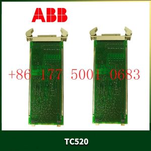
PDAA401 3BSE017234R1 Электрический фильтр ABB
Швейцария, и входит в десятку крупнейших швейцарских транснациональных корпораций.PDAA401 3BSE017234R1
химическая, нефтехимическая, фармацевтическая, целлюлозно – бумажная, нефтепереработка; Оборудование приборов: электронные приборы, телевизоры и оборудование для передачи данных,
генераторы, гидротехнические сооружения; Каналы связи: интегрированные системы, системы сбора и распространения;PDAA401 3BSE017234R1Строительная промышленность: коммерческое и промышленное строительство.
Figure 4 Tool Framework
2.3Smart component creation
Call the Rotator component: This component is used to allow the rotatable grinding rotor to rotate during simulation to simulate the real grinding scene. In the
parameters of the Rotator component, set the reference to object, the reference object to the frame l, and the object to a copy of the rotor. (2) The rotary grinding rotor
can be rotated, and the speed is l20mm/s (the speed of the grinding head will affect the quality of the finished product) ), the reference center axis is: axis (based on frame
l, centerpoint x, y,: set to 0, 0, 0, Axis set x, y,: 0, 0, l000mm).
Call the Attach component: This component is used to allow the rotatable grinding rotor to be integrated with the tool body. When the tool body is installed
on the flange, it can follow the movement of the flange. In the parameters of the Attach component, set the sub-object to be a copy of the rotor (2) for the rotatable
polishing rotor, and the parent object is the tool body of a copy of the rotor. The offset and orientation are
based on the offset of point B relative to the origin. For setting, you can use the measurement tool in Robotstudio software to measure, and then set the parameters
after measurement.
Verification: Install a copy of the rotor tool body onto the robot flange, and then click Execute in the Attach component. You can observe whether the position of the
rotatable grinding rotor is correct at this time. If there is a deviation, adjust the position in time, as shown in the figure. 5 shown.
Figure 5 Tool installation
2.4 Create tool coordinate system
Use the six-point method to create the tool coordinate system Too1data on the robot teach pendant at the center of the rotor. Change the tool coordinate
system to Too1data in the basic options. At this time, click on the robot manual linear and you can drag the robot to move linearly at will.
2.5 Creating trajectories and programming
Determine the trajectory: According to the requirements of the work task, design the grinding trajectory around the workpiece and determine the trajectory
points and transition points required for the grinding trajectory. The grinding action process is shown in Figure 6.
Setting I/O and programming: Yalong IY-l3-LA industrial robot deburring and grinding system control and application equipment adopts 0sDC-52 6/o
communication board, the address is 10, Do1 is the digital output signal, the address is 1 . First set the I/O board, then set the I/O digital output signal Di1,
and then program on the simulation teaching pendant. The procedure is as follows:
PRoCmain()
setDo1: Set the Do1 signal to allow the external grinding rotor to start rotating.
waitTime1: The robot stays in place and does not move, waits for 1s, and lets the polishing rotor turn to the specified speed, transition
MoveAbsjjpos10NoEoffs,v1000,z50,Too1data1: The robot moves to the initial point jpos10 above point p10. Point jpos10 is used as the starting
point and end point of the robot”s action.
Move4p10,v1000,z50,Too1data1: Move straight line grinding to point p10
Move4pL0,v1000,z50,Too1data1: Move straight line grinding to pL0 point
Move4p30,v1000,z50,Too1data1: Move straight line grinding to point p30
Move4p40,v1000,z50,Too1data1: Move straight line grinding to p40 point
Move4p10,v1000,z50,Too1data1: Move straight line grinding to point p10
MoveAbsjjpos10NoEoffs,v1000,z50,Too1data1: The robot moves to the initial point jpos10 above point p10
waitTime1: wait 1s, transition
ResetDo1: Reset the Do1 signal to stop the rotor ENDPRoC
2.6 Simulation design and verification
Simulation design: Create a smart component to input the Di1 signal, and use the Di1 signal to simulate the external polishing start signal to
execute the Rotator component and Attach component of the smart component to achieve the visual effect of rotating and polishing the polishing rotor.
In the workstation logic design, the smart component input Di1 signal is associated with the robot Do1 signal, so that the robot signal Do1 can control
the smart component input Di1 signal, thereby controlling the start and stop of the rotation of the polishing rotor.
Verification: In the program of the teaching pendant, first set the pp command to move to Main, and then set the robot startup mode to automatic.
Click play in the simulation of Robotstudio software to verify whether the trajectory is consistent with the assumption, and optimize the path in time for
problems existing in the simulation.
3Summary and outlook
This design is based on the programming simulation of the Yalong Y4-1360A industrial robot deburring system to control the grinding robot workstation.
It covers aspects such as creating a workstation, setting
up tools, creating smart components, creating tool coordinate systems, creating trajectories, programming, simulation design, and verification. Starting
with it, the polishing simulation of the workstation is realized through the smart component function of Robotstudio software. The animation effect is intuitive
and lifelike, which not only facilitates teaching demonstrations, but also facilitates program debugging, and has application value for both production and teaching.
In the planning and design of the workpiece grinding trajectory, according to the different roughness and grinding amount process requirements of the
workpiece, the rotation speed, feed speed, feed amount, and grinding angle of the grinding rotor are also different. The feed amount can be adjusted in
time according to the on-site conditions. , feed speed, rotor speed, grinding angle and other parameters. After appropriate adjustments, the motion trajectory is written with the
corresponding program on the Robotstudio software to further reduce the possibility of robot collisions and singular points contained in the trajectory
during the actual debugging process. ,Optimize paths and improve debugging efficiency.
LNL-1320 Lenel Interface Module
LKB2211 SUPERRAC LKB Superrac Fraction Collector
KT3315TA Cutler-Hammer K-FRAME TYPE KT TRIP UNIT
KE310 REXROTH Electric Drives and Controls
KSY-464.80 R6XFWS113SB-1 GEORGII KOBOLD Ac Servo Motor
K0143AAAN FOXBORO Power supply module
JZNC-XRK01D-1 Yaskawa Framework of equipment
JANCD-XCP01-1 YASKAWA Central processing unit control board
JAMSC-B2902V Yaskawa MODULE PLC RELAY OUTPUT
ISH070/60017/0/0/00/0/00/10/00 SCHNEIDER SERVO MOTOR
IRDH375 BENDER Insulation monitoring device
IRDH275-435 BENDER Insulation monitoring instrument
HC703BS-E51 Mitsubishi Motors-AC Servo Motor
HA-SC23 Mitsubishi Motors-AC Servo
GV7-RS150 Schneider circuit breaker
WSWE24-2B230 SICK Compact photoelectric sensor
PCD235B1101 3BHE032025R1101 ABB Unit of processor
ST31276A SEAGAET DISK
PT-VME330A Performance Technologies 16-Channel VME Communications Controller
UFC911B106 3BHE037864R0106 ABB Control the mainboard
IS200TVIBH2BBB GE TERMINATION BD VIBRATION MARK VI BOARD
IS420ESWBH2A GE Ethernet / IONet Switch
IS200TPROH1BBB GE Mark VI Board
IS200TBCIH1BBC GE Mark VI Board
IS200TBAIH1CCC GE TERMINAL BOARD ANALOG
31C075-503-4-00 Sew Eurodrive Movitrac 31C 7.5kW AC Drive
IC695ETM001-EK GE Ethernet Interface module
FCP270 P0917YZ FOXBORO Field Control Processor 270
DS200TCTGG1AFF GE SIMPLEX TRIP BOARD
IC695CPU315-CD GE 1 GHz Central Processing Unit
DS200TCRAG1ACC GE Relay Output Board
DS200TCPDG2BEC GE POWER DISTRIBUTION BOARD
F7130A HIMA Power Supply Module
DS200TCPDG1BEC GE Power Distribution Board
EPL10200 LENZE DRIVE CONTROL
60M100-00 Bently Nevada Programmable logic controller processor
33VM52-000-29 PACIFIC SCIENTIFIC Low Inertia PMDC Servomotor in the VM Series
80VD100PD.C022-01 B&R ACOPOSmicro inverter module
85UVF1-1QD Fireye Self-Checking Flame Scanner
1756-RM/A Allen-Bradley ControlLogix enhanced redundancy module
EPQ96-2 DEIF digitally controlled electronic unit
EMC400-EPWS ETHERWAN 4-Slot Din-Rail Media Converter Chassis
EGCP-2 8406-121 Woodward microprocessor-based complete generator control
EASYGEN-3500-5 Woodward turbomachinery Genset controller units
DKC02.3-040-7-FW Rexroth DKC Drive Controllers
DMP10.24 RPSTECH Power supply module
CPAR-04AE-13574 PECKER Servo driven drive
8521-0312 UG-10D Woodward Processing Unit MODULE
CPC210 Bachmann Controller Module
AHD70E4-44S KOLLMORGEN SERVO MOTOR
C825KN10 Cutler-Hammer 200A 600V Magnetic Contactor
8307292002 EATON CAN BRIDGE CONNECTOR 10 I/O MODULE
3500/22M 138607-01 Bently Nevada Standard Transient Data Interface Module
8200-226 Woodward Servo Position Controller
6410-007-N-N-N Pacific Scientific Stepper Drive
6435-001-K-N PACIFIC SCIENTIFIC STEP DRIVER 66VDC
8440-2165 SPM-D2-11 Woodward Synchronization and Load Share Control


Reviews
There are no reviews yet.